

Ways to Measure Main Bearing Clearance of Marine Engine
A marine engine comprises of several types of bearings which support the rotating and reciprocating crankshaft, camshaft, and cross head of the engine, enabling the marine engine to perform the desired operation of power generation. It is very important to maintain a good quality and quantity of lubricating oil to all these bearings in order to avoid breakdown of the engine.
What is Main Bearing?
Bearings, which directly supports and are in contact with the crankshaft of the engine are known as main bearings.
The main bearing of a marine engine supports the long running crankshaft throughout the engine length. This makes it imperative to check the condition of the bearing at regular interval of time.
Why Clearance is Measured?
The clearance measurement of the main bearing determines the amount of wear down the bearing has been subjected to.
The clearance of the bearings will depend on the size of the engine but for a 900mm bore engine the clearance is between 0.40 and 0.70 mm with a maximum allowable of 0.9mm. Similarly for a 500mm bore engine the allowable clearance is provided as between 0.4mm and 0.55mm
All the modern bearings are usually of the thin wall type with non adjustable clearance. If the bearing clearance has reached it’s maximum limit or the bearing got damaged, it cannot be reconditioned and needs to be changed.
Reason for Bearing Clearance
The increase in bearing clearance indicates the worn out of bearing material, which may be due to following reasons:
Journal Defect: A journal is a polished part of the crankshaft accommodating the bearings, helping the crankshaft setup to rotate. If the journal pin is defective, the bearing clearance will increase at a faster rate. Reason for journal pin damage:
- Overheating: Bearing materials are made from the material which have better embeadiility and shock absorbing property. In case of any defects, bearing material will worn out saving the shaft journal. If the engine is run long even after the bearing material is wiped out, the shaft will get overheated leading to damage to the journal developing cracks and increase in the hardness of the journal.
- Hairline Cracks: The journal pin is under stress when the crankshaft is in operation. If the stresses on the journal is localized and increased, a crack may form in such high stress area specially near fillet radii and oil grooves. To get rid of this, expert technician can do pin grinding. This will change the size of the bearing to be used for the grinded pin and also de-rate the engine.
- Metal Contact: Similar problem to the abrasive damage.
If there is metal to metal contact due to wiping of the bearing material, or dirty lube oil containing small metal particles- squeezing, scoring, cracking and pitting will occur on the journal pin
Bearing Defect: If the journal of the crankshaft is fine but the defect is in the bearing itself, it may be due to following reasons:
- High oil temperature: Not maintaining the lube oil temperature supplied to the bearing will decrease the oil thickness and lead to metal contact
- Oil viscosity: Correct viscosity oil should be used with high viscosity index else bearing material will not be able to float on the oil film and contact the journal metal
- Oil Load carrying capacity: Load carrying capacity of the oil is an extremely important factor, When the ship is operated in higher load, which in turn is transmitted to the main bearings, a low load carrying capacity oil will fail in such situation leading to bearing damage
- Oil pressure: Maintaining the continuous oil supply and correct oil pressure will ensure oil film between bearings and journal is never run out to maintain the oil lubracation
- Engine ambient temperature: If the engine is started in cold ambient temperature, the oil supply during the start to the bearings will not be sufficient leading to damage to bearing material. The bearing whicih is placed farthest to the oil supply pump will be affected largely.
- Spark erosion: It may lead to overheating of Main engine bearings caused by improper lubrication resulted by cavities. Read More here.
Methods to Measure Bearing Clearance
There are various types of methods adopted by different marine engine manufacturers to measure the clearance of main bearing of marine engine. Following are some of the most prominent methods used onboard ships to measure the clearance of main bearing:
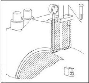
1) Bridge with Depth Gauge
This method is used in SULZER 2 stroke marine engines where the bearing‘s shell is removed along with the keep (the bearing shell is lined with the keep). After that a bridge is fitted over the top of journal pin, from port to starboard, making a bridge over the crankshaft with two ends supported on the cross girder.
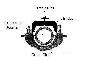
A simple vernier type depth gauge is then inserted in the hole provided on the bridge and the scale of depth gauge is rested on the crankshaft pin. The total depth on the scale is measured and compared with the previous reading and the reading in the manual for calculating the wear down of bearing.
In old model SULZER engines, a collar is provided in the bearing shell along with a small hole. Thus without removing the keep, the bridge is fitted adjacent to the keep and the depth gauge is used from the hole provided in the shell to measure the shell wear down.
2) Bridge With Feeler Gauge
In some engines, after removing the shell and the keep, the bridge is installed as explained in the above point. Also, in place of depth gauge, a feeler gauge is used to measure the clearance between the journal pin top and the bridge bottom. The bridge used here is different in terms of height and the gap between the pin and the bridge is very less as compared to that of the bridge used in the above mentioned method.
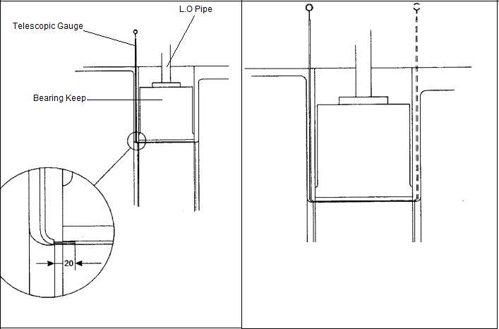
3) Telescopic or Swedish Feeler Gauge
In engines like MAN B&W, this is the most common method used to measure the bearing clearance of the top shell. In this method there is no need to remove any connection or keep for measuring the clearance.
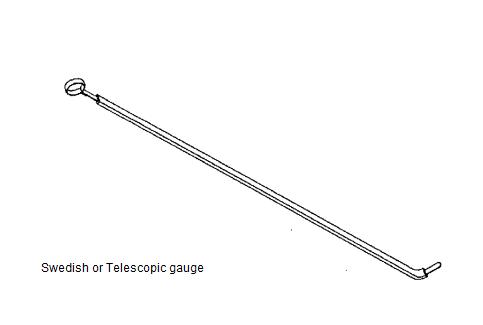
The telescopic gauge is inserted between the gap of the crank web and the bearing keep. When the tip reaches the shell top, the feeler is inserted between the shell and the pin to check the clearance.
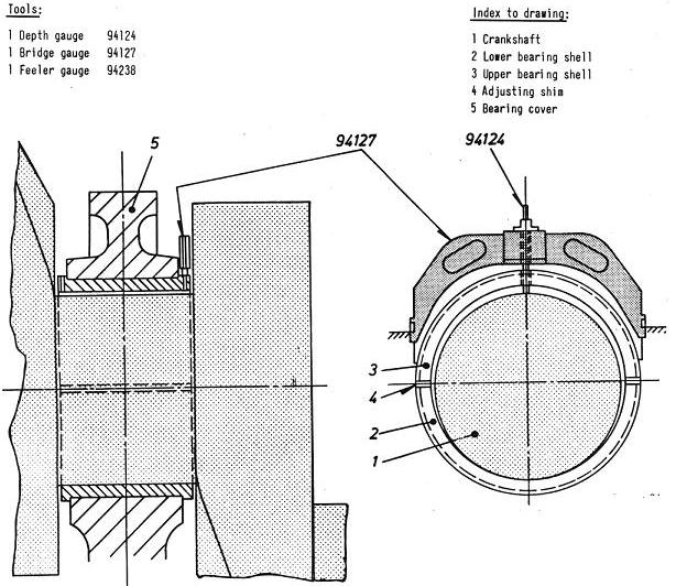
4) Dial type Depth Gauge
This method is used in new MAN B&W engines (SMC-C) which does not require the top keep to be removed. The lube oil pipe connection screw hole is in the bearing keep which can be accessed from the hole on the bearing shell.
The dial gauge is inserted in this screw hole and the reading is taken as the clearance for upper shell.
5) Lead wire – The Traditional Method
This is a traditional method and to be used when no other alternative or tools are present. In this method, lead wire is inserted at different positions between bearing and pin. The bearing housing is tightened. Ensure not over squeezed the wire more than 1/3 rd of original diameter. General Method for taking clearance using lead wire:
- Turn the crank shaft to set the crank at TDC position.
- remove locking and slacken the nut to lower the bottom half with bolts.
- Three lengths of lead wires to be inserted or laid circumferential in the bottom half at three different places.
- Close the bottom half into position and tighten the nut to its rated tightening torque.
- Open and lower down the bottom half again.
- Remove the lead wires and take the measurement.
It must have within the limit, if out of limit, the bearing shell must be replaced with new ones or readjust the clearance by adjusting shims.
Do you have info to share with us ? Suggest a correction

About Author
An ardent sailor and a techie, Anish Wankhede has voyaged on a number of ships as a marine engineer officer. He loves multitasking, networking, and troubleshooting. He is the one behind the unique creativity and aesthetics at Marine Insight.

Subscribe To Our Newsletters
By subscribing, you agree to our Privacy Policy and may receive occasional deal communications; you can unsubscribe anytime.
I have been examinating out some of your articles and i can claim pretty
good stuff. I will surely bookmark your website.
Hi can you please tell me fourth method Depth gauge from LO pipe screw in which SMC-C engine model?
Because all the manuals I see it is telescopic gauge method.TIA
@Ashfaq: You can find it in 6S46MC-C model too
Can you specify the position of crank Web while taking the clearance in above methods.
This might give a clear picture: https://forums.marineinsight.com/forum/marine-engineering/3619-auxiliary-main-engine-big-end-bearing-clearance
Sir if clearance is more bearing is worn right. So by adjusting clearance by removing shims,won’t it affect bearing or it’s like using damage bearing and will result in engine damage??
Thank you very much, I got more information & increased my knowledge,Please send me more informations about Gas turbines parts and all types of clearances (GT-10 ABB Stall).
Hi sir I have doubt in method 5. Is that main bearing clearance or bottom end bearing clearance.
Thank you Waseem. Please use our forums for detailed Q&A.
https://forums.marineinsight.com/