

What is an Inert Gas or IG System on Ships?
Oil tankers carry oil of different grades and quality, having the property to produce flammable vapours and gases when loaded for transportation.
Even with no cargo on board, there can be harmful flammable gases present in the hold.
When the vapour produced by an oil cargo is mixed with a certain concentration of air primarily containing oxygen, it can result in an explosion which results in damages to the property, marine pollution and loss of life
For safety against such explosions, an Inert gas system is used onboard. It can be through as a separate inert gas plant or flue gas produced by a ship’s boiler.
What is Inert gas and Inert gas system?
Inert gas system is the most important integrated system for oil tankers for safe operation of the ship.
Inert gas is the gas that contains insufficient oxygen (normally less than 8 %) to suppress the combustion of flammable hydrocarbon gases.
The inert gas system spreads the inert gas over the oil cargo hydrocarbon mixture which increases the lower explosion limit LEL (lower concentration at which the vapours can be ignited), simultaneously decreasing the Higher explosion limit HEL (Higher concentration at which vapour explodes). When the concentration reaches around 10 %, an atmosphere is created inside the tank in which hydrocarbon vapours cannot burn. The concentration of inert gas is kept around 5% as a safety limit.
Components and description of IG system:
The following components are used in a typical inert gas system in oil tankers:
1. Exhaust gases source: inert gas source is taken from exhaust uptakes of boiler or main engine as contains flue gases in it.
2. Inert gas isolating valve: It serves as the supply valve from uptake to the rest of the system isolating both the systems when not in use.
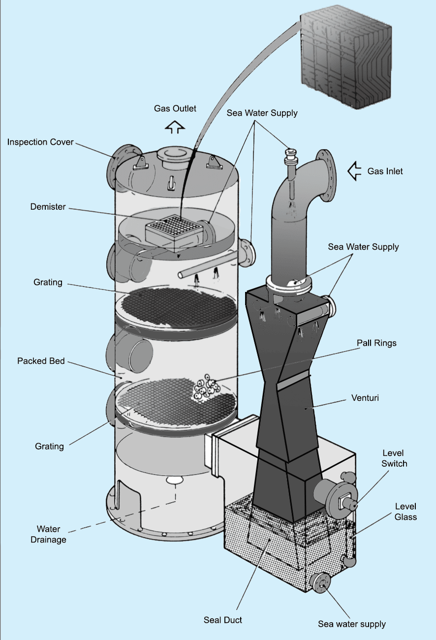
3. Scrubbing tower: Flue gas enters the scrub tower from the bottom and passes through a series of water spray and baffle plates to cool, clean and moist the gases. The SO2 level decreases up to 90% and gas becomes clear of soot.
4. Demister: Normally made of polypropylene, it is used to absorb moisture and water from the treated flue gas.
5. Gas Blower: Normally two types of fan blowers are used, a steam-driven turbine blower for I.G operation and an electrically driven blower for topping up purposes.
6. I.G pressure regulating valve: The pressure within the tanks varies with the property of the oil and atmospheric condition. To control this variation and to avoid overheating of the blower fan, a pressure regulator valve is attached after blower discharge which re-circulates the excess gas back to the scrubbing tower.
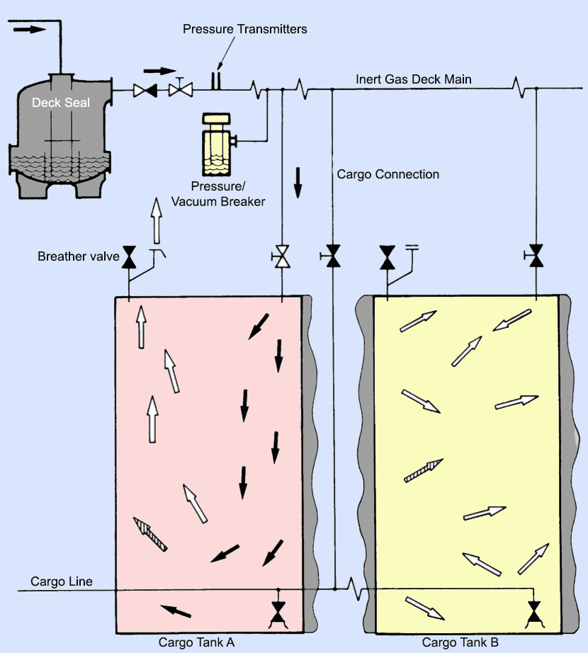
7. Deck seal: The purpose of the deck seal is to stop the gases to return back which are coming from the blower to cargo tanks. Normally wet type deck seals are used. A demister is fitted to absorb the moisture carried away by the gases.
8. Mechanical non-return valve: It is an additional non-return mechanical device in line with the deck seal.
9. Deck isolating valve: The engine room system can be isolated fully with the deck system with the help of this valve.
10. Pressure Vacuum (PV) breaker: The PV breaker helps in controlling the over or under pressurization of cargo tanks. The PV breaker vent is fitted with a flame trap to avoid the fire igniting when loading or discharging operation is going on when in port.
11. Cargo tank isolating valves: A vessel has number of cargo holds and each hold is provided with an isolating valve. The valve controls the flow of inert gas to hold and is operated only by a responsible officer in the vessel.
12. Mast riser: Mast riser is used to maintain a positive pressure of inert gas at the time of loading of cargo and during the loading time it is kept open to avoid pressurization of the cargo tank.
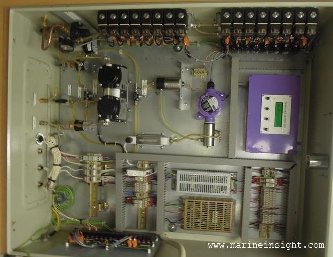
13. Safety and alarm system: The Inert gas plant is provided with various safety features to safeguard the tank and its own machinery.
Following are various alarms (with Shutdown) incorporated in the Inert Gas plant on board the ship:
- High Level in scrubber leads to alarm and shutdown of blower and scrubber tower
- Low-pressure seawater supply (approx. 0.7 bar) to scrubber tower leads to alarm and shutdown of blower
- Low pressure seawater supply (approx. 1.5 bar) to deck seal leads to alarm and shutdown of blower
- High inert gas temperature (approx. 70 deg C) leads to alarm and shutdown of blower
- Low pressure in line after blower (approx. 250mm wg) leads to alarm and shutdown of blower
- Oxygen content high (8%) leads to alarm and shutdown of gas delivery to deck
- Low level in deck seal leads to alarm and shutdown of gas delivery to deck
- Power failure leads to alarm and shutdown of blower and scrubber tower
- Emergency stop leads to alarm and shutdown of blower and scrubber tower
Following are various alarms incorporated in the Inert Gas plant:
- Scrubber low level
- Deck seal High level
- Low O2 Content (1%)
- High O2 Content (5%)
- Low lube oil pressure alarm
Working of Inert Gas Plant
The basis of inert gas production in the IG plant is the flue gas generated from the ship’s boiler. The high-temperature gas mixture from the boiler uptake is treated in an inert gas plant which cleans, cools and supplies the inert gas to the individual tanks via PV valves and breakers to ensure the safety of the tank structure and atmosphere.
The system can be divided into two basic groups:
a) A production plant to produce inert gas and deliver it under pressure, by means of blower(s), to the cargo tanks.
b) A distribution system to control the passage of inert gas into the appropriate cargo tanks at the required time.
Brief working procedure
- Boiler uptake gases are drawn to the scrubber unit via flue gas isolating valve(s) to the scrubber unit.
- In the scrubber unit the gas is cooled, cleaned and dried before being supplied to the tanks.
- Motor-driven inert gas blowers supply the treated gas from the scrubber tower to the tanks. They are mounted on rubber vibration absorbers and isolated from the piping by rubber expansion bellows.
- Regulation of gas quantity delivered to the deck is taken care of by the gas control valves and the deck pressure is managed by the pressure controller. If the deck pressure is lower than the set point the output signal will be raised to open the valve more, and vice versa if the deck pressure is lower than the set-point. These valves will then work in cooperation to keep both the deck pressure/blower pressure at their respective setpoint without starving or overfeeding the circuit.
- Before entering the deck line, the gas passes through the deck water seal which also acts as a non-return valve automatically preventing the back-flow of explosive gases from the cargo tanks.
- After the deck seal, the inert gas relief is mounted to balance built-up deck water seal pressure when the system is shut down. In case of a failure of both the deck seal and the non-return valve, the relief valve will vent the gases flowing from the cargo tank into the atmosphere
- The oxygen analyser which is fitted after the blower separates the “production” and “distribution” components of the plant and analyzes the oxygen content of the gas and if it is more than 8%, it alarms and shutdowns the plant
Disclaimer: The authors’ views expressed in this article do not necessarily reflect the views of Marine Insight. Data and charts, if used, in the article have been sourced from available information and have not been authenticated by any statutory authority. The author and Marine Insight do not claim it to be accurate nor accept any responsibility for the same. The views constitute only the opinions and do not constitute any guidelines or recommendations on any course of action to be followed by the reader.
Do you have info to share with us ? Suggest a correction
Latest Ship Safety Articles You Would Like:

About Author
An ardent sailor and a techie, Anish Wankhede has voyaged on a number of ships as a marine engineer officer. He loves multitasking, networking, and troubleshooting. He is the one behind the unique creativity and aesthetics at Marine Insight.


Subscribe To Our Newsletters
By subscribing, you agree to our Privacy Policy and may receive occasional deal communications; you can unsubscribe anytime.
Could you please contact me I am the head of engineering department and I would like to purchase some books for the student library. Thanks
Stan.
why seal air valves provide in ig system ? what precaution to be taken regarding tank pressure when a tanker goes from hot to cold region and vice versa ?
what is the difference between pv valve and pv breaker?
As far as I know. PV Breaker is like the last line of defense, if PV Valves doesn’t work. They are normally separated or programmed to operate at different Pressure.Vacuum Values. In the ship I am in. PV Valves are set at 200mbar when over press. and the PV Breaker are set to 230mbars over pressure.
How can i troubleshoot the iG system when the IG seawater pump and Blower will not start automatically so that the IG system wll be ready to start?I already checks connections,relay,power supply,valves that activating some alarms that can trigger the emergency stop.thank you very muh in advance for the reply…
It would be good to see some pictures about each component of de inert gas system, as the Pressure Vacuum (PV) breaker, Cargo tank isolating valves, Scrubbing tower. if anyone has pictures send it to me! Thanks!!
what is the different between the mast riser & the pv\v
thanks & best regard
This question has recently been answered in our forums: https://forums.marineinsight.com/forum/marine-engineering/2298-what-are-at-the-major-difference-between-mast-riser-and-pv-valve
Please ask further queries in the forum for speedy and multiple replies.
What is the purpose of sealing air in Inert Gas plant.
why IGG shutdown after delivery..Now cargo tank empty
RESOLUTION MSC.365(93)
(adopted on 22 May 2014)
AMENDMENTS TO THE INTERNATIONAL CONVENTION
FOR THE SAFETY OF LIFE AT SEA, 1974, AS AMENDED
5.5.1.2 For tankers of 8,000 tonnes deadweight and upwards constructed on or
after 1 January 2016 when carrying cargoes described in regulation 1.6.1 or 1.6.2,
the protection of the cargo tanks shall be achieved by a fixed inert gas system
in accordance with the requirements of the Fire Safety Systems Code, except that
the Administration may accept other equivalent systems or arrangements, as
described in paragraph 5.5.4.
how many pv valves are required in a tanker.
what type of system you would expect to find on a VLCC built after 2000 if it is not fitted with an inert gas system?
why we need to maintain o2 contain more than 1% in ig system ? what happen if it is less?
What precautions to be taken to ensure that no moisture and/or water from Inert Gas entered the cargo tanks
@Sweetiezack: Demister is used which is made of polypropylene. It is used to absorb moisture and water from the treated flue gas.
Is it possible to have soot blowed away in seawater around the vessel, if I have any problem with the non return valve or anyother component of the system?
What are the safeties associated with this system?
@Dhananjay: Request you to please post this query in our forums- https://forums.marineinsight.com/
Hi our inert gas system don’t seem to be working properly on our vessel.When we go in to a empty tank the system takes up to 4 to 5 hours to get the tank up to 30 m/b. when you check the oxygen content at that time, its still anywhere between 18 to 21% in the tank.
what kind of volume should you be getting from the system on start up in to an empty tank.
Thank you in advance for your help.
Hi Anish, Is there is any difference between the PV valve and PV breaker?
@Azra: Pressure vacuum valve or PV valve in the ventilation system will prevent either PV valve cover or under pressure. They are set usually so that tank pressure of about 0.14 bar will lift the main valve (The smaller valve will lift along with it) and release excess pressure. PV valve operates overtime when there is a change in the tank pressure.
PV breaker is used to release abnormal rise or drop of Pressure in Cargo Tanks. Will operate only when there is an abnormal deviation in the pressure.
PV Breaker is like the last line of defense if PV Valves doesn’t work. They are normally separated or programmed to operate at different Pressure. PV Valves are set at 200mbar when overpressure and the PV Breaker is set to 230mbars overpressure.
NITROGEN (N2) BASED INERT GAS SYSTEM ALONGWITH ACCESSORIES
dear sir plas giv e the compititive price of the following
HI , Is it a condition that the water chiller cooler must be running to pass on “aeration mode “?
thanks
Check the scrubber tower water sensor. You may have to ingrese the delta time. This sensor could inhibit the start ip.
Thank you David for helping out ??
Good day ..i need to know ,if yours ha something about M Engine ELECTRONIC SYSTEM/ WARTSILA/ SULZER ..about de new technology, even need to pay
When the iG plant is shutdown, the cooling water should be let on the scrubber for atleast how many hours.
i need complete IG manual