

15 Things To Consider While Using Radar On Ships
The radar is one of the most used equipment systems onboard ships. It is designed for detecting and tracking targets a considerable distance. Needless to say, it’s of great practical value to the navigators.
Proper use of radar and radar plotting aids in both restricted visibility and clear weather can help prevent collisions and ensure the safety of the ship. Accidents can occur if the watch keeping officer is not fully conversant with the operation of the equipment. For reliable interpretation, it is essential that the radar operating controls be adjusted properly.
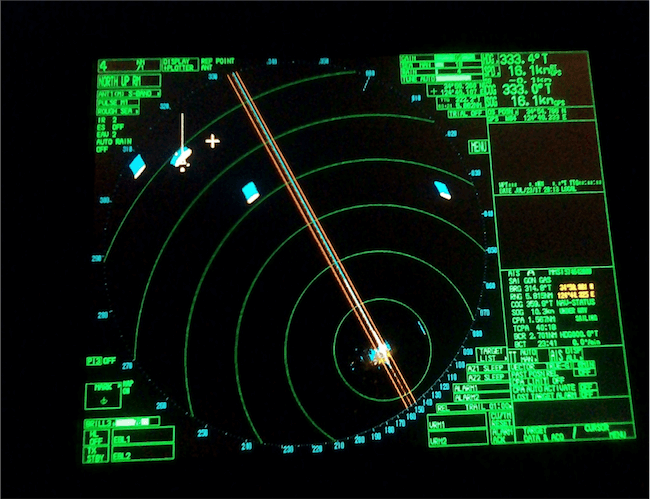
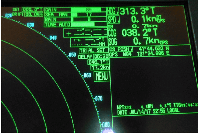
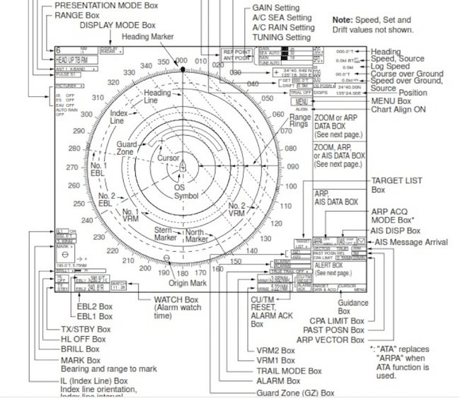
In this article, we would like to discuss how to interpret and understand a radar screen display. Below attached is a picture of a radar screen and the keyboard. This article will help to understand the basic approach to the use of marine radar.
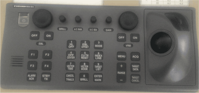
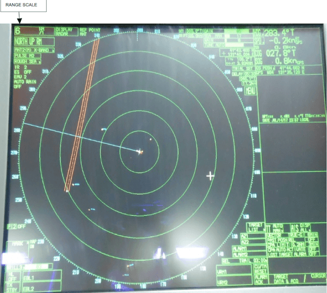
1. CHOICE OF RANGE SCALE: Appropriate range scales should be used depending on the prevailing circumstances and conditions of the environment the ship is in. Where two radars are used, one radar can be kept on a longer range scale to obtain advance warning of the approach of other vessels, changes in traffic density, or proximity to the coastline. The other radar can use a short range scale, which helps to detect smaller targets easily. Use the RANGE key in the keyboard to select the range desired. The ‘+’ key increases the range whereas the ‘-’ key decreases the range.
The range scale shown in the picture below is 6 miles and each fixed range ring is pre-determined at an interval of 1 mile.
2. RANGE MEASUREMENT: Measurement of range to a target can be achieved either by the fixed range rings or the Variable Range Marker (VRM). The fixed range rings appear on the screen with a pre-determined interval depending upon the range scale in use and provide a rough estimate of the range to a target. The current interval is shown in the upper left position on the screen. Count the number of rings between the center of the display and the target to measure the range to a target. The Variable Range Marker’s diameter can be increased or decreased so that the marker touches the inner edge of the echo of the target thus giving more accurate range measurements. There are two sets of VRMs available and they appear as dashed rings. Press the VRM ON key to display either of the VRMs.
3. BEARING MEASUREMENT: Electronic Bearing Lines is used to take the bearing of targets. The EBL extends from the own ship position to the circumference of the radar screen. If bearing remains constant with decreasing range, the risk of collision exists.
4. GAIN: The gain control on the keyboard is used to adjust the sensitivity of the radar. It should be so adjusted that the background noise is just visible on the screen. In simple words, if the gain is set too low, weak echoes may be missed while excessive sensitivity yields too much background noise. Echoes from two targets on the same bearing can appear as a single pip on the PPI or the radar screen. A reduction in the gain setting is therefore required in this situation.
5. REDUCING SEA CLUTTER / RAIN: If rain or sea clutter is set too low, targets will be hidden in the clutter whereas if set too high can cause targets to disappear from the radar screen. The radar can also detect rain, snow or hail clutter in the same manner as normal targets. The A/C RAIN and A/C SEA control is used to adjust the rain and sea clutter respectively. The scroll wheel is rolled clockwise or anticlockwise to increase or decrease the clutter.
6. OF CENTRE DISPLAY: Own ship position can be displaced to expand the view field without switching to a large range scale. However while doing so care should be taken that at least one mile of viewing range is kept on the aft of the ship to view targets on the ship’s aft or ships trying to overtake own vessel. The cursor can be put to the position where you wish to move the ship’s position and then press the OFF CENTRE key on the keyboard.
7. TARGET TRAILS: Target trails can be of great assistance to the radar observer in making an early assessment of the situation. The trail can either be relative or true. Relative trail shows relative movement between own ship and target. True trail presents true target movements depending on their over the ground speed and course. Relative trails give an early indication if a close quarter situation is developing or risk of collision exists. Relative trails when combined with true vectors gives an indication of the relative movement of other vessels and the risk they present. The trail time can be adjusted as per requirement.
8. PI (PARALLEL INDEX) LINES: This is a useful method of monitoring cross track tendency. It helps us to assess the distance at which the ship will pass a fixed object on a particular course. The index line is drawn parallel to the planned ground track and should touch the edge of a radar echo of a fixed object, at a range equal to the desired passing distance. Any cross track tendency (such as caused by a tidal stream, drift or current) becomes apparent as the target moves off the parallel line. This technique can be used in both relative and true motion. Use the trackball to select the PI line number box. Select a PI line number and push left button to turn it off or on. Roll the scroll wheel to adjust the PI line orientation (between 000°T to 359.9°T).
9. HEADING/SPEED/COURSE: The top right corner of the radar screen display shows the heading, speed, course, and speed over the ground, own ship position, and the source. Speed can be entered from a log(STW) or GPS(SOG) or manually.
Speed over the ground (SOG) IS the speed of the vessel referenced to the surface of the earth. Speed through the water (STW) is the speed of the vessel referenced to the water in which it is navigating. In general, STW is used for radar collision avoidance to provide a more accurate indication of the target’s aspect and SOG is used for navigation. Right click the speed box to select the source for speed.
Right click the own ship position box to select the source of position data- GPS1/2 or DEAD RECKONING.
10. BRILLIANCE: The overall brilliance of the screen can be adjusted according to lighting conditions using the BRILL KEY by turning clockwise or anti-clockwise. The brilliance box at the bottom left corner of the screen provides various palettes and other options as shown below. Select the item needed and roll the scroll wheel to adjust the brilliance. The brilliance menu can be seen by right-clicking on the brilliance box.
11. WATCH ALARM: the function of the watch alarm is quite similar to that of BNWAS. The watch alarm sounds the audio alarm at selected time intervals to help keep regular watch of the radar picture. The countdown starts from the value set. Officers often need to spend time inside chart table thus sometimes forgetting to keep a radar watch. Watch alarm can, therefore, be used to avoid being occupied for a long time inside radio room or chart room. The ALARM 1 and 2 in the picture below is used to set up the alarm. The ALARM ACK key should be pressed to silence the alarm.
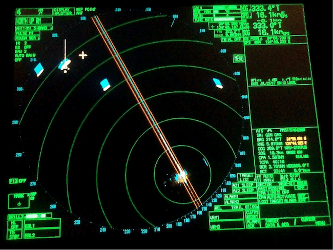
12. VECTOR MODE: target vectors CAN BE SET relative to own ship’s heading (RELATIVE) or North (TRUE). When determining close quarter situation or risk of collision exist use of relative vectors is preferred. It is a good practice to switch between true and relative vectors to gain a better appreciation of the navigational situation. When using a true vector, own ship and other ship moves at their true speed and course. True vectors can distinguish between moving and stationary targets. The relative vector helps to find ships on a collision course. A ship whose vector passes through own ship’s position is on a collision course. The Vector Length can be adjusted to the required time frame. It is useful to have both relative and true information visible simultaneously; this can be achieved by selecting relative vectors with true trails. Combining true vectors with true trails will give no indication of the relative movement of other vessels and the risk they present. Shift the cursor to vector mode box and left click to select the vector required. The vector time can also be selected using the left button.
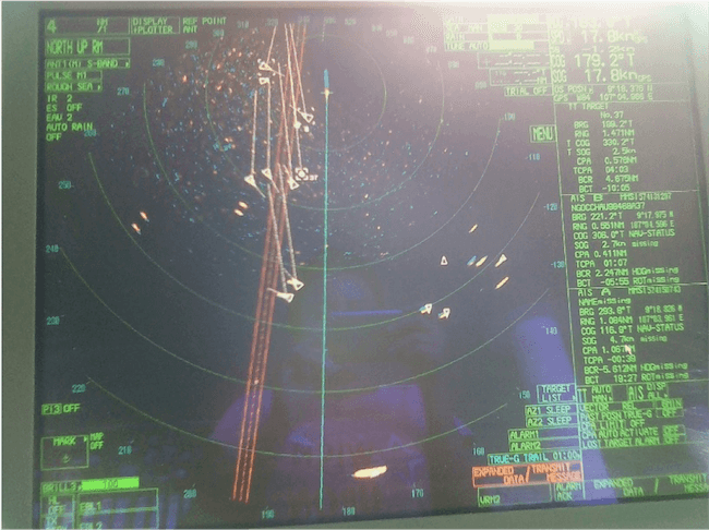
In the picture above, the vector mode is relative and trail used is true.
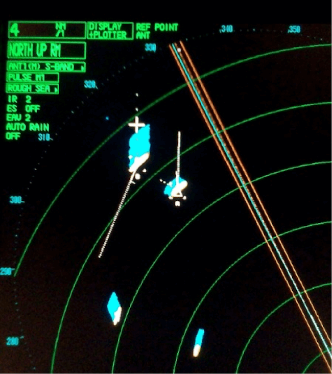
12. PAST POSITION: The past position Is a useful indicator. These history dots are placed at a fixed preset interval. Dots in a straight line at even spacing indicate a steady course and speed by the targets. Any changes can be noted as the spacing becomes uneven. Change of course will not be shown in a straight line. A curve in the trail indicates an alteration of course whereas the change in the spacing of the plots indicates a change in the speed of the target. The past data can also help the observer to check whether a particular target has maneuvered in the recent past, possibly while the observer was away from the display on other bridge duties. However past position, if used can clutter the screen and should be avoided in heavy traffic as the plots of different targets start crossing and overlapping each other and should be used with caution.
13. MARK: The MARK menu enables the officer to mark any prominent target or a point of particular interest. For example, you can use the trackball to select the desired mark from the mark box at the left side of the screen. Also, you can drop anchor mark by entering the Anchor coordinates provided by VTS in port areas in the Mark menu. Right-click to open the mark menu and use L/L to enter the coordinates.
14. TARGET TRACKING/ AIS DATA BOX: appears on the right side of the radar screen. It provides information of automatically or manually acquired targets including display of range, bearing, course, speed, CPA and TCPA, BCR and BCT. The target list provides a comprehensive data display of all targets being tracked. To acquire a target on the radar screen, simply move the cursor to the target and left click. The TARGET ACQUIRE key on the keyboard can also be used to acquire the target. The CPA limit box can be used to set the range and time for CPA as required. If a target is predicted to breach the CPA limits, the alarm will sound and/or displayed.
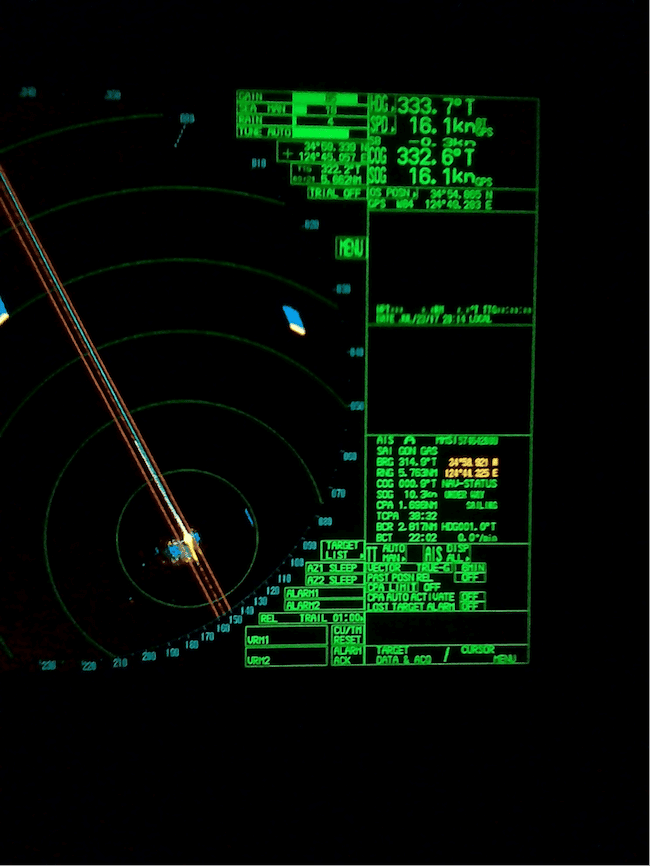
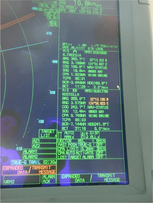
15. PRESENTATION MODES: Radar users must clearly understand what they are seeing. North up relative motion is the normal default radar display format. Within that relative and true vector and trails can be selected. The North Up mode shows the targets in their true (compass) directions from own ship, North being maintained up on the screen. The heading marker changes its direction according to the ship’s heading. If the TRUE motion is used, own ship and other moving targets move according to their course and speed. Fixed targets such as landmasses appear as stationary echoes. In the pictures above, the presentation mode used is North Up Relative Motion.
The radar display provides the operator a bird’s eye view where other targets are portrayed relative to own ship. It is an invaluable aid to navigation. Proper use and close monitoring of the radar especially in reduced and restricted visibility can help avoid the close quarter situation and/or collision. It is therefore important that all radar users understand its use and have a thorough knowledge of the equipment.
Disclaimer: The authors’ views expressed in this article do not necessarily reflect the views of Marine Insight. Data and charts, if used, in the article have been sourced from available information and have not been authenticated by any statutory authority. The author and Marine Insight do not claim it to be accurate nor accept any responsibility for the same. The views constitute only the opinions and do not constitute any guidelines or recommendation on any course of action to be followed by the reader.
The article or images cannot be reproduced, copied, shared or used in any form without the permission of the author and Marine Insight.
Do you have info to share with us ? Suggest a correction

About Author
Paromita has completed graduation in Nautical Science and is presently preparing for 2nd mate exams. Besides sailing, she loves to read books and travel. She has also won many awards in music.
Latest Marine Navigation Articles You Would Like:


Subscribe To Our Newsletters
By subscribing, you agree to our Privacy Policy and may receive occasional deal communications; you can unsubscribe anytime.
Web Stories

Could you please explain why do we choose input for ships position in radar ? I mean we can choose if we want to use GPS1/2 to get ships SOG and COG. But why do we need DR mode in radars ?
Becouse DR gives you corrected and precise position of the ship from satellites.
We have 10 Nos of Furuno Marine Radar Model Furuno 1932 of our fleet at Jeddah Islamic Port I would like to know how I can erase the Radar Range rings from screen ? Could you please help me .I will be appreciated for your kind attention.
What speed to be maintained while in coastal passage or river passages?
@Amal: Every country will have its own local regulation for speed. However, the ship’s manoeuvring speed to be maintained when crossing such areas.
pls help me answer this question:what do you understand by close bearing ,open bearing and steady bearing of the target ?Please explain.
Pls anwer..how to deterrmine risk of collision when using true vectors..
some captain likes to set in true vector and not relative even though its much preffered
what is the advisable range settings of the radar when your navigating in open sea? it is advisable to frequently set to short range in that said area? thanks..
Can someone please explain me the difference between course through water and course over ground ?
What are the safety precautions to be taken while repairing radar?