

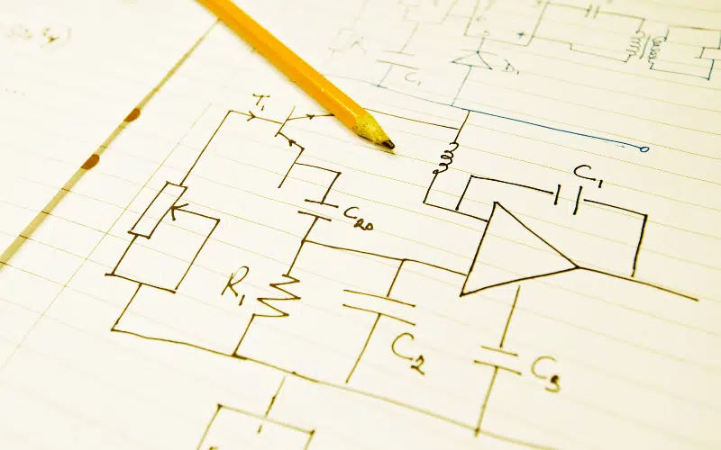
Amplifier Circuit or Operational Amplifier (op amp) Used on Ship
An Amplifier or an operational amplifier (op-amp) circuit is commonly used in the automation, control and other electronic circuits for marine applications.
The applied input signal is usually a voltage or a current signal. The purpose of an amplifier is to produce an output signal larger than that of the input signal.
Use of Amplifier Circuit
As the name suggests, the purpose of an amplifier or an op-amp is to amplify or increase the input signal to produce an output signal which is much larger than that of the input, with a similar waveform as that of the input.
The main change in the output signal will be the increase in the power level. This additional power is supplied by a D.C voltage which is externally provided. The output signal is controlled by the input signal in an amplifier.
In Electronic components, which are compact, small-signal amplifiers are commonly used devices as they have the capability to raise a relatively small input signal to a larger magnitude. For example from a Sensor such as a photo device, into a much larger output signal to drive a relay, lamp or loudspeaker.
Few devices on the ship you can find amplifier circuit:
- It is used to amplify the audio signals (speaker, VHF, PA system Ship horn)
- It is used as a voltage and current regulator
- It is used as an analogue to digital converter & vice versa
- It is used as a servo amplifier in motor
- The output signal from the amplifier is supplied to a relay in a circuit
- It is used in Gyrocompass
- It is used in the Engine room, deck and other alarms
- It is used in various Sensors
- It is used in electrical protection systems
Various electronic circuits are classed as amplifiers, from Operational Amplifiers and Small Signal Amplifiers to Large Signal and Power Amplifiers.
The amplifier can be further classified depending:-
- on the size of the input signal
- on the physical configuration
- on how it processes the input signal, that is the relationship between the input signal and the current flowing in the load.
Most of the electrical and electronic circuit contains the amplifying device, such as a Transistor, Field Effect Transistor or Op-amp, which has two input terminals and two output terminals (the ground being common) with the output signal being much greater than that of the input signal as it has been “Amplified”.
Operation of Amplifier Circuit
The input of the amplifier consists of differential input voltage V+ input and V-input and this difference in the voltage is amplified to produce a large output. Therefore the op-amp equation can be given by
V o/p = [(V+)- (V-)] x A o/l
Where A o/l is open-loop gain of the amplifier.
In an op-amp, the magnitude of A o/l is huge which gives a large output even when the input differential is small.
An Operational Amplifier is a three-terminal device that consists of two high impedance inputs; one called the Inverting Input, marked with a negative or “minus” sign, ( – ) and the other one called the Non-inverting Input, marked with a positive or “plus” sign ( + ).
Ideal Amplifier
We can now specify the characteristics for a perfect amplifier from our discussion above with regards to its Gain, meaning voltage gain:
- The amplifier’s gain, ( A ) should remain constant for varying values of the input signal.
- Gain is not be affected by frequency. The same amount must amplify signals of all frequencies.
- The amplifier’s gain must not add noise to the output signal. It should remove any noise that already exists in the input signal.
- The amplifier’s gain should not be affected by changes in temperature giving excellent temperature stability.
- The gain of the amplifier must remain stable over long periods of time.
Characteristics of Ideal Op-Amp or Operational Amplifier
An “ideal: or perfect operational amplifier (Op-Amp) is a device with certain unique characteristics such as infinite open-loop gain Ao, infinite input resistance Rin, zero output resistance Rout, unlimited bandwidth 0 to ∞ and zero offsets (the output is exactly zero when the input is zero).
It has a high output gain.
It has high input and low output impedance
The bandwidth is in the very high range.
Getting ideal machinery or circuit is impossible. Energy losses in an instrument are always present, but choosing a close to the ideal amplifier will provide the best operational characteristics in the electrical/electronic circuit it is installed.
Disclaimer: The authors’ views expressed in this article do not necessarily reflect the views of Marine Insight. Data and charts, if used, in the article have been sourced from available information and have not been authenticated by any statutory authority. The author and Marine Insight do not claim it to be accurate nor accept any responsibility for the same. The views constitute only the opinions and do not constitute any guidelines or recommendation on any course of action to be followed by the reader.
The article or images cannot be reproduced, copied, shared or used in any form without the permission of the author and Marine Insight.
Do you have info to share with us ? Suggest a correction

About Author
An ardent sailor and a techie, Anish Wankhede has voyaged on a number of ships as a marine engineer officer. He loves multitasking, networking, and troubleshooting. He is the one behind the unique creativity and aesthetics at Marine Insight.

Subscribe To Our Newsletters
By subscribing, you agree to our Privacy Policy and may receive occasional deal communications; you can unsubscribe anytime.