

Understanding Components and Design of Exhaust Gas System of Main Engine On Ship
On ships, the work done by marine engines to keep the plant running for propelling a ship requires burning of fuel. The energy converted inside the cylinder of the engine is not 100% efficient conversion as part of it is lost in the form of exhaust gases.
The modern exhaust gas system of marine engines is designed in such a way that the unused gases coming out of the cylinders are further directed to turbocharger and exhaust gas boiler to recover most of the waste energy from the same.
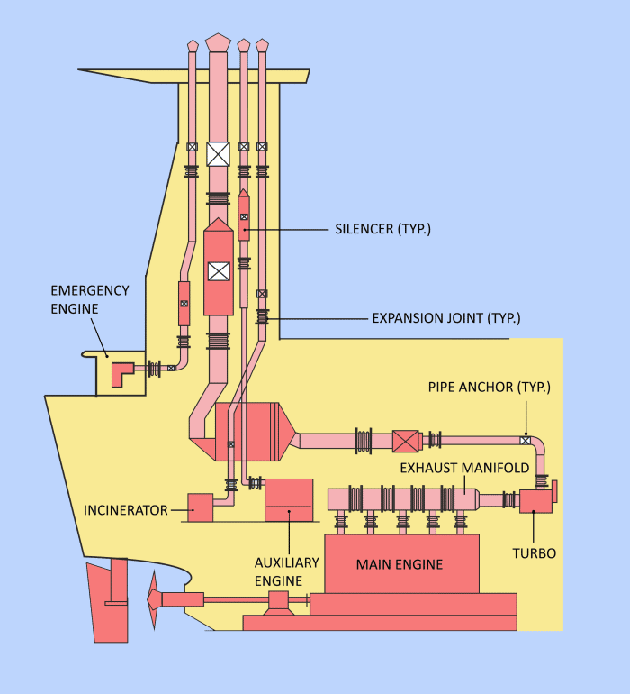
Components for the Exhaust Gas system of Engine:
To utilise the maximum energy from the waste gases, the exhaust gas system of marine engine is provided with the following components:
- Exhaust gas pipes
- Exhaust gas boiler
- Silencer
- Spark arrester
- Expansion joints
Exhaust gas-piping system for marine engine:
The exhaust gas piping system conveys the gas from the outlet of the turbocharger(s) to the atmosphere. For designing the exhaust piping system, following important parameters must be observed:
- The exhaust gas flow rate
- Maximum back force from exhaust piping on turbochargers
- Exhaust gas temperature at turbocharger outlet
- Maximum pressure drop within the exhaust gas system
- Maximum noise level at gas outlet to atmosphere
- Sufficient axial and lateral elongation ability of expansion joints
- Utilisation of the heat energy of the exhaust gas.
The Exhaust gas from the cylinder unit is sent to exhaust gas receiver where the fluctuating pressure generated from different cylinders are equalised. From here, the gases which are at constant pressure are sent to turbocharger where waste heat is recovered to provide additional scavenge air to engine.
The most important thing to consider while designing the exhaust piping system is the back pressure on the turbocharger. The back pressure in the exhaust gas system at specified Maximum Continuous Rating (MCR) of engine depends on the gas velocity, and it is inversely proportional to the pipe diameter to the 4th power. It is general ship practice to avoid excessive pressure loss within the exhaust pipes, the exhaust gas velocity is maintained about 35m/sec to 50m/sec at specified MCR. The other factors which affect the gas pressure are the installation of EGB, Spark arrestor etc. in the path of exhaust gas travel.
At the specified MCR of the engine, the total back pressure in the exhaust gas system after the turbocharger (as indicated by the static pressure measured in the piping after the turbocharger) must not exceed 350 mm WC (0.035 bar). In order to have a back pressure margin for the final system, it is recommended at the design stage to initially use a value of about 300 mm WC (0.030 bar).
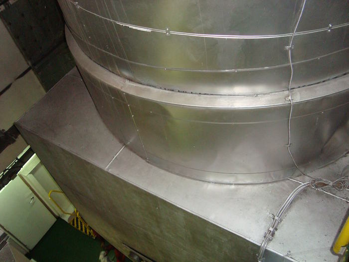
Exhaust gas boiler:
Exhaust gas boiler is considered to be one of the most efficient waste heat recovery system designed for a ship. When the ship’s propulsion plant is running at it’s rated load, the auxiliary boiler can be switched off as the EGB can generate the required steam for various ship’s systems. The exhaust gas passes an exhaust gas boiler, which is usually placed near the engine top or in the funnel.
The efficiency of the EGB will be affected by the pressure loss of the gases across the boiler and the parameters governing the pressure loss (exhaust gas temperature and flow rate) are affected by the ambient conditions. The recommended exhaust pressure loss across the EGB is generally considered as 150 mm WC at specified MCR. If the exhaust system is not provided with additional equipment (spark arrester or silencer), the pressure loss value can be considered little bit higher then the value stated above (150 mm WC at specified MCR).
Silencer
The engine room plays a major role in high Noise levels in the accommodation, which is now moderated under Maritime Labor Convention.
The Exhaust gas piping system are generally close to accommodation hence the reduction of noise form them is important. To get the noise level, it is recorded at a distance of 1m from the exhaust gas pipe outlet edge at an angle of 30° provided the exhaust gas system of the engine are without EGB or silencer.
Silencer is used to reduce the noise level in the exhaust gas manifold and they are generally placed after the EGB. The Conventional silencers consist of absorptive and reactive chambers. They are constructed for a gas velocity of 35m/s and the reactive chamber is only effective at one frequency.
The latest design of silencer consist of three chambers to overcome the limitation (of being effective at one frequency)
The three elements are composed of a reactive element for attenuation of lower frequencies, a resistive element-absorptive silencer to tackle with higher frequencies, and a combination element of both reactive and resistive elements. This set up will reduce the noise effectively without increasing the back pressure on the turbocharger by tuning the elements to match the engine over the noise range.
Spark arrester:
The low load operation of marine engine tends to produce partially burnt carbon deposits and soot with the exhaust gas piping system of engine. As the exhaust gases produced after combustion are rich with oxygen, these partially burnt carbon particles are discharged from the exhaust funnel as highly dangerous spark.
A spark arrester can be fitted in the exhaust piping system to prevent sparks from the exhaust gas being spread over deckhouse. It is placed at the end of the exhaust gas system of the engine.
The new design of spark arrester helps the gases to create rotatory movements by forcing them to pass through fixed number of angel positioned blades. The heavy carbon particles are smoothly collected in the designed soot box, which can be cleaned or drained as required.
They can be combined with silencer as one unit to save space or cost.
The main disadvantage of a spark arrester is considerable pressure drop. For main engine of a ship, it is recommended that the combined pressure loss across the silencer and/or spark arrester should not be allowed to exceed 100 mm WC at specified MCR.
Expansion joints
The Exhaust gas system of engine experiences huge temperature variations. It is not possible to construct the entire exhaust piping system in one single piece hence; multiple sections are joined to complete the system. When the engine is standstill, the temperature of the exhaust pipe may vary from 10 to 40 deg C (depending upon the surrounding environment or geographical location of the ship) and when the engine is up and running, the exhaust system temperature crosses 200 deg c. This major temperature variation requires need of joints to safely absorb the heat-induced expansions and contractions of pipes and tubing systems.
For this purpose, bellows and expansion joints are used. They are designed accurately to make sure that they are able to withstand the stresses and avoid cracks brought about by the continuous change in the temperature of the system. As per Boyle’s Law- When tubing is subjected to high-temperature fluids, pressure also builds up. Expansion joints are needed to bear the extra force that accumulates.
Expansion joints are used in tubing and piping systems and Bellows are generally used to connect exhaust gas pipes to the funnel.
The expansion joints are to be chosen with an elasticity that limits the forces and the moments of the exhaust gas outlet flange of the turbocharger as stated for each of the turbocharger makers.
The Expansion joints are placed at various places spreading it in the exhaust gas piping system of the marine engine.
Above we have discussed the most important components and functions of Exhaust Gas System of Marine Engine on ship. If you feel we have missed something, please feel free to comment.
Do you have info to share with us ? Suggest a correction

Subscribe To Our Newsletters
By subscribing, you agree to our Privacy Policy and may receive occasional deal communications; you can unsubscribe anytime.
Web Stories


About Author
An ardent sailor and a techie, Anish Wankhede has voyaged on a number of ships as a marine engineer officer. He loves multitasking, networking, and troubleshooting. He is the one behind the unique creativity and aesthetics at Marine Insight.
Please inform.What type of valve and joints are used in these system?Also where the soot goes of EGB.?
@Zubair:
As mentioned in the article, expansion joints are used.
The soot is cleaned at regular intervals by doing EGB washing. Other method to clean the soot is to perform soot blow operation.
No Not Applicable Name of goods Sign code/ P/N Long description Manufacturer Unit Quantity
1 00.076.001.01503 Butterfly valve actuator – TAUR.-60 ACTUATOR P/N: 186159-37 (186159-32)- 186159-37 (186159-32) Solar Turbines/OEM PCE 1
2 00.076.001.02274 Belt cooling fan lubricant -GATES BELT. V – P/N: 5VX 810 (998093C1) – 5VX810 Solar Turbines/OEM PCE 20
3 00.076.001.01562 Air intake – ELEMENT.FILTERAIR P/N: 700473 Cl – CL700473 Solar Turbines/OEM PCE 64
4 00.076.001.01563 Air intake – ELEMENT.FILTER.AIR P/N: 700474C1 – 700474Cl Solar Turbines/OEM PCE 64
5 00.076.001.00932 Sleeve nozzle – TAUR.-60 GASKETJNJECTOR P/N: 136856-1 (1 pack = 4 pce) – 136856-1 Solar Turbines/OEM PCE 168
6 00.076.001.01117 Gas pressure control valve – KlT,REGULATOR.,REPLACEMENT P/N: 179964K101B – 1779964K101B (179964K200B) Solar Turbines/OEM PCE 2
7 00.076.001.01021 Pressure regulator – TAUR.-60 REGULATOR;PRESS P/N: 186273-1 186273-1 Solar Turbines/OEM PCE 2
8 00.076.001.00889 Diaphragm pressure regulator – TAUR.-60 DIAPHRAGM.VALVE.CONT P/N; 990535C1 – 990535C1 Salac Tuibines/OEM PCE 4
9 00.076.001.02283 Exhaust pipe outside the engine room -BELLOWS, EXPANSION AX-5644-100- AX-5644-100 Solar Turbines/OEM PCE 1
10 00.076.001.02282 Accessories for exhaust pipes -HARDWARE KIT, FLANGE AX-5614-102- AX-5614-102 Solar Turbines/OEM PCE 1
11 00.076.001.02281 Sealed exhaust pipe – CASKET SPIRAL 80-30550-100 – 80-30550-100 Solar Turbines/OEM PCE 5
Actually as per boyle’s law ,temperature is constant. So according to gay lussac’s law temperature increases with respect to pressure increases.
What does it mean exhaust gas damper system and where is used?
@Selios: Do you mean vibration dampers which are connected to exhaust line?
inredible post whatsapp 7838748668 get in touch
Related to the exhaust gas velocity, is there any references so that I can study more about it?
What kind of rules to design exhaust gas system ?
Once, I got a report that the exhaust gas pressure after turbocharger is negative. is that possible? like he told, for very low loads, this pressure can be as less as -25 mmWC. But then, other marine engineer whom I consulted told me this is not correct and the pressure sensor needs calibration or same is faulty. What are your thoughts?