

How to Draw and Read Line Diagrams Onboard Ships?
Understanding the operations and intricacies of machineries can be arduous and challenging task onboard ships. For every engineer officer, preliminary theoretical knowledge of day to day operations and piping systems is important for taking cognizance of complicated machinery operations. The hierarchy on board further defines and demands the engineers in their first stint onboard to trace the piping diagrams in order to have thorough understanding of different symbols and lines from the facsimiles provided onboard.
Usually, a typical line diagram would look like a printed labyrinth and could be difficult to understand. It is hence suggested to keep them for reference and trace them physically.
The junior rank is generally the in-charge of daily transfers related to sludge and bilge waters, under the directions of the second engineer and thus he should begin his enterprise with the same approach.
To instigate with the process of plotting line diagrams, one should always start with the highest or lowest point in the system, specifically with a tank that supplies or is being drained to, taking all safety precautions.
The tank being drawn without scale, should be marked with the outlet valves or inlet valves, along with the sophisticated remote closing devices having pneumatic control arranged for operations external to the engine room.
The tanks should further be marked with the air pipes, thermometers, level gauges, overflow pipes and electronic high and low level alarms.
Sounding pipes must be considered and their position in the tank must be thought of, whether in aft or forward of the tank.
Manhole doors and other mountings aid the cleaning and inspection of particular tanks and they must also be drawn with a symbol representing important details. Tracing the mountings serve an additional aid to know abnormality and the normal operating parameters of the system. With any deviation, a problem can be encountered and dealt without chasing the track of breakdown maintenance.
The point of the pipes leaving the tank should be noted. Further, the lines should be traced with the subsequent valves marked with their types ( some require turning the floor plates if they lie buried inside). This would help to know the leakages and get them rectified at the earliest.
Special attention should also be paid to the lagging clad steam lines and valves which could cause a burn if handled carelessly. Valves placed below the floor plates could be difficult to identify and memorize, and thus should be marked with the respective names from the system diagram by a felt tip pen for future references.
Moving further, each and every pump along with its auxiliary should be marked with strainers and filters. The change over lever in the duplex filter should be carefully noticed, along with the purging cock and drain respectively.
The type of pump should be considered along with their application in handling different fluids in the particular system. The same should be studied and the reasons should be framed for their application in that system. Relief valves, if provided, on the discharge side of the pump must be looked upon, laying emphasis on the fact that they are not present on the discharge side of centrifugal or roto dynamic pumps.
Procedure
Following ways should be taken for tracing a system for line diagram:
– Start from the highest or the lowest point. Never start from any random or middle point.
– Ensure to know the color coding of various piping systems on ship (e.g. bilge lines are normally yellow, sludge line is black, fresh water lines are blue, sea water lines are green etc.)

*Color coding will differ depending on company SMS
-Ensure to wear all PPEs specially helmet, gloves and safety shoes as for tracing you may need to go below the floor plate where space constraint is prominent
– Always carry a good torch as a pipe being traced may crossover another pipe in dark corners or in bilge area below floor plate which if misread, will lead to wrong interpretation of line diagram
– Know different types of valves and their universal symbol. While tracing the line diagram, draw the valve as per the type
– Any crossover or overlapping line must be clearly shown in the diagram. Crossover lines are connected to each other and overlapping lines do not touch. They can be indicated by a gap or using a jump curve/ half circle indicating it is not connected to the below line

– Ensure to mark the fwd-aft, port and starboard position in the diagram. This is very important to pin point the location of any object in the diagram
– While tracing the line, draw the diagram in rough hands. Once the tracing is complete, draw it in a neat paper with approximate scale.
– Compare your diagram with the line diagram provide in ship’s library
– If you see any line or valve etc. is missed after comparing from ships diagram, do check it locally as ships often undergo modifications, which is generally not included in the original line diagram
– If you pointed out any modification in the line diagram, mark it as “modification”
– Never trace and draw two systems in one diagram.
– Lastly, make sure a senior officer has checked the diagram you have drawn for any general fault
Every system has its peculiar intricacy and a concept involved. Fuel Oil system, if considered, is divided into 4 specific systems, mainly bunkering, fuel oil transfer system, cleaning and separation systems and the Fuel supply system (to boiler, Main engine, Generator, etc.). This should be noted while tracing and drawing diagrams.
In general, “cushy” diagrams must be drawn first and then one should head for fuel supply system which is integrated in the machinery i.e. fuel supply lines in the main engine generator engine or boiler firing line etc.
Considering the cooling sea water line, one could easily miss the mountings on the sea chest filter, which has a distinct cock to purge off air before it enters the system. Ensure not to miss such details.
Three way valves in a particular system, such as cooling fresh water system must also be emphasized upon and its functioning should be studied, centering the type of control involved in its operation.
Computer based training is another source of potential knowledge and concept, which could be studied for the systems prior tracing the lines physically, if provided.
Keeping safety in conscience and considering the engine room a hazardous place, the valves ought not to be tampered while carrying out tracing procedure. This is specifically for the junior engineers with little knowledge of the systems.
The systems once drawn should be verified with the senior engineers and could be then understood in detail with the operations and transfers. A rational approach with the theoretical concept can well be carried out on paper, if done religiously.
Drawing and reading the line diagrams is the basis of understanding each and every detail of the machinery operations onboard and the above approach should be followed in order to master the art of line diagram plotting and drawing.
Do you have info to share with us ? Suggest a correction
Latest Shipboard Guidelines Articles You Would Like:


Subscribe To Our Newsletters
By subscribing, you agree to our Privacy Policy and may receive occasional deal communications; you can unsubscribe anytime.
Approach towards good engineering skills …
Must be read by new upcoming joiners becoz the topic that discussed above is very very obligatory for new joiners nd beginners
If u got hold to this one it’s just Lyk
Holding a neck of ships engine room nd just u want to see up nd down for types of machineries which r installed …..
good one brother..
What are the three best software programs to draw diagrams in ship?
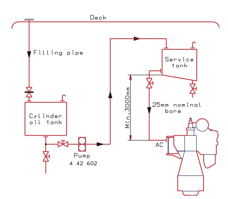
What is the Diagram of main engine lub. oil system?
Dear Rudy,
We have a complete ebook for important engine room line diagram which is free with our mega combo pack- https://www.marineinsight.com/marine-ebooks/mega-combo-pack/
Can i have explanation on why thrust bearing is before flywheel ( with reference to going from engine to propeller side)
Very article and not only juniors but senior engineer when ever appointed on ship must spare some time for understanding line diagrams and then life will be very easy. With understanding valves and random areas diagrame it may work but during any emergency etc it will be difficult to locate the actual problem.
Buenas noches, talves les ofenda mi apreciación, pero para alguien q se hiso de abajo, con mucho sacrificio aprender piping , no es nada nuevo esto, salvo la tecnología q cambia a cada instante, nada cambia, los circuitos son los mismos siempre. Una entrada, intermediario si hisiere falta y una salida, nada nuevo.
Forget the software for drawing piping diagrams use good hardware, note book, pencil and eraser.